Fit-based Thickness Filter
The Fit-based Thickness Filter calculates the thickness of one or more semi-transparent films on a substrate by fitting a physical reflectance model to the provided measured reflectances.
Category |
|
Node |
|
Parameters |
Number of layers: The number of layers to fit. For each layer the user must specify a different material, and the filter will calculate a separate thickness value. Minimum Thickness: (per-layer parameter) The minimum thickness for the initial comparison step. Maximum Thickness: (per-layer parameter) The maximum thickness for the initial comparison step. Film Material: (per-layer parameter) The material of the film whose thickness is to be determined. Substrate Material: The material of the substrate on top of which the films are present. Quality: A quality setting that provides a
trade-off between performance and accuracy of the
filter. A higher value will lead to improved
accuracy at the expense of performance, and
vice-versa. The special value Custom Quality Settings: This allows the user
to import custom settings provided by LuxFlux for
very specific applications for which the default
quality settings do not provide a good trade-off.
The Quality parameter must be set to |
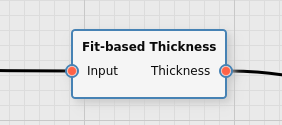
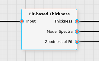
Inputs |
Input: spectral reflectance data |
Outputs |
Thickness: the thickness values of the layers. Model Spectra: the spectra of the physical model corresponding to the fitted thickness values for each pixel (optional) Goodness of Fit: a measure for how well the fit worked for each pixel (optional) |
Effect of the Filter
The filter calculates the thickness of one or more films of material on top of a substrate. It uses repeated refraction of light at the boundaries of the films to model an expected spectrum of the film and provides a fit based on that physical model. The films must be at least slightly transparent for this to work.
The filter assumes the following stacking of the various materials:
Air
Film 1
Film 2
…
Film N
Substrate
The channels of the first output correspond to the thickness values in the order that the layers were defined in.
The filter will provide the thickness values per input spectrum. For example, if a HSI cube is provided as the input of the filter, for each x and y value of the cube a set of thickness values will be provided. If a list of spectra is provided, a set of thickness values will be calculated for each individual spectrum provided.
In a first step the best match to a set of precalculated reflectance curves for various thicknesses is performed, after which an iterative algorithm refines the calculation. The Quality parameter fine-tunes the parameters of this process to allow the user to easily trade off accuracy and performance. The Minimum Thickness and Maximum Thickness parameters provide the range of initial reflectance curves that are used to determine the best match. This range is best kept as small as possible for performance reasons. However, if the actual thickness measured is not within that specified range, the calculation of the filter will likely be inaccurate and might even produce implausible results.
Note
The Minimum Thickness and Maximum Thickness do not ensure that the result of the algorithm of this filter stay within that range, they only determine how the algorithm starts determining the thickness. It is useful to add a Clamp Values filter after this filter to ensure that the thickness values are only within a given range.
Which ranges of thickness this filter can measure to which accuracy will depend on the material, the spectral range of the camera, and the spectral resolution of the camera.
In order to have an adequate physical model for the reflectance curves
that the film produces at varying thicknesses, the user must provide
information about the materials of both the substrate and the films
themselves. (It is assumed that only air is between the film and the
camera lens.) This information must be specified in form of
wavelength-dependent refractive index curves with both a real part
(n for the refractive index itself) as well as imaginary part
(k for the absorption coefficient). Clicking on the ... buttons
when editing the Film Material and Substrate Material parameters
will open the refractive index database editor, which allows the user
to select from a set of materials or import their own. How to use the
database editor is described in the section
Refractive Index Database Editor.
The quality parameter allows the user to select the degree of accuracy they wish to have:
Custom: a custom set of quality settings (see below)
1: minimal accuracy, but best performance. It is useful for getting a feel for the thickness of a large unknown sample measurement where the total thickness range is huge, but the result will only be a rough approximation
2: slightly better accuracy, good performance. This setting provides reasonably accurate results while still being quite fast. It is the default setting and recommended for most inline applications.
3: high accuracy, medium performance. This setting is recommended for most applications where a decent accuracy is key but performance is still not completely irrelevant
4: very high accuracy, low performance
5: extremely high accuracy, very low performance
In some very difficult cases the default quality settings may not be adequate to achieve a proper fit. For this reason a custom quality setting is available. In those cases, please contact LuxFlux for an in-depth discussion on the issue related to a specific use case, and LuxFlux may be able to provide a file with specialized parameters that may be imported. They may also be exported into a file again in case the original settings file provided by LuxFlux have been lost but a model using them is still available.
For analysis purposes, in addition to the output that contains the thickness values, other outputs may be enabled conditionally. The following sections describe the additional outputs that may be enabled.
Optional Output: Fitted Spectra
It is possible to enable the output Fitted Spectra. For each input spectrum it will output the spectrum of the internal physical model for the specific thickness value that was calculated.
The primary application for this is to compare the measured spectra to the spectra of the physical model used and to see how well these match and to more easily identify problems.
It may also be useful to verify that the supplied refractive index curves lead to the expected behavior.
Enabling this output will decrease the performance of the filter somewhat in addition to the quality setting, because the model spectrum has to be calculated for the specific thicknesses for each input spectrum after the thickness calculation has already completed.
Optional Output: Goodness of Fit
The output Goodness of Fit may be enabled conditionally. It will
provide a numerical quantity that indicates how good the fit between
the measured spectra and the model spectra are. A value of 0
indicates a very bad fit, a value of 1 indicates an excellent fit.
Enabling this output in addition to the Fitted Spectra output will not significantly impact the performance of this filter. Enabling it without also having Fitted Spectra enabled will have a similar performance impact that enabling Fitted Spectra has. (Because the calculation of the model spectra has to be performed if this output is active, even if no output is returning those spectra to the user.)
Thickness Ranges
Which range of film thickness can be estimated by this filter depends strongly on the material of the film, as well as the spectral range and resolution of the camera that has been used to measure the reflectance spectra used as the input of this filter.
The following table gives an overview of the typical thickness ranges that this filter can be used for when measuring a single film of SiO2 (with an average refractive index of 1.454):
Camera |
Minimum Thickness |
Maximum Thickness |
HSI Camera in VIS Range (400nm - 1000nm) |
50 nm |
10 μm |
HSI Camera in NIR Range (900nm - 1700nm) |
0.5 μm |
50 μm |
These numbers are estimates to give a rough indication; the details will strongly depend on the specific material used as well as the camera.