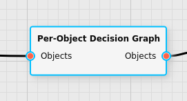
Per-Object Decision Graph Filter Reference
The per-object decision graph filter allows the user to specify a ruleset that makes classification decisions based on attributes of objects.
Category |
|
Node |
|
Parameters |
Decision Graph: the decision graph itself (see below) |
Inputs |
Objects: a list of objects as generated from an object detection filter |
Outputs |
Objects: the list of objects augmented by the result of the decision graph |
Effect of the Filter
The filter takes a list of objects as its input. This may be the object list coming directly from an object detection filter, or a list that was modified by a object processing filter (such as the Per-Object Statistics filter).
The output will be the same object list, but with a user-specified classification ruleset applied to it.
The decision graph may change the object list in the following manner:
It may add a class column to the object list (or update the existing one) that assigns each object a unique group from the list of groups in the model.
It may add a column containing a list of integer quality values (the integer type can be specified by the user) for each object. For example, it is possible to assign two quality values that are 8bit unsigned integers to each object depending on the values of existing columns of each object.
Assigning a group as the object’s class
fluxTrainer models allow for the definition of groups that may be used to label input data. Certain classification filters allow for the use of machine learning algorithms to determine the best group that matches input data and automatically assign it to either individual pixels or objects as a class.
The per-object decision graph filter extends this by allowing the user to manually assign a previously defined group as a class to an object, but using a fixed ruleset instead of a machine learning algorithm.
The groups that are assigned by this filter in this way do not need to have any input data assigned to them, they may only exist as a possible classification result.
Assigning quality values
As an alternative to (or in addition to) assigning a class to an object it is also possible to define quality parameters that are set based on the specified ruleset.
Quality parameters are an array of one or more integers. The type of integer (8, 16, 32, or 64 bit; signed or unsigned) and the number of quality parameters are specified by the user.
For example, it is possible to define a single 16bit unsigned integer as a quality parameter, or to use two signed 32bit integers. When editing the decision graph (see below) the user may specify these parameters as well as the ruleset that fills these values.
The semantics of these quality parameters are completely up to the user.
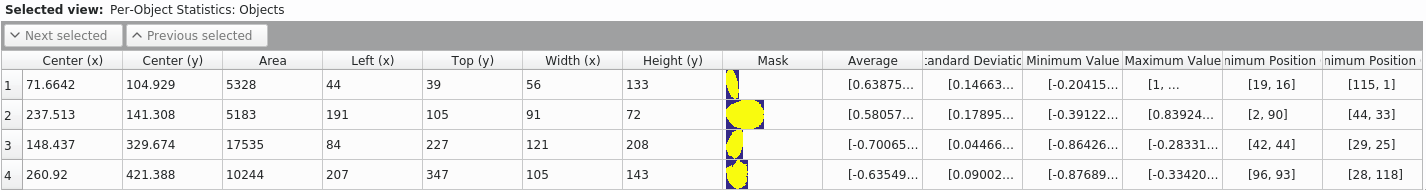
Example of Filter Effect
As an example, take the following list of objects as the input of the decision graph filter:
When applying a decision graph that introduces a quality parameter, the resulting table could look like this:

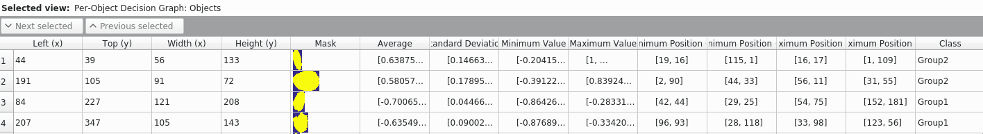
When applying a decision graph that assigns a group as the class of the object, the resulting table could look like this:
Decision Graphs
Decision graphs may be edited by clicking on the Edit… button of the Decision Graph parameter of the filter. It will open a new window that allows for editing the decision graph.
Note
The input of the filter should be connected before opening the editor so that the editor can know which input columns may be used for conditions.
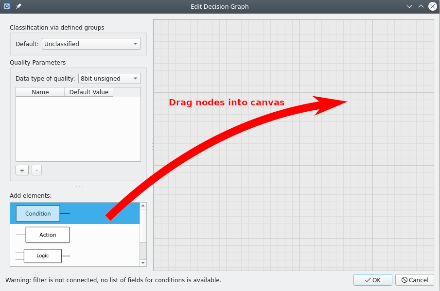
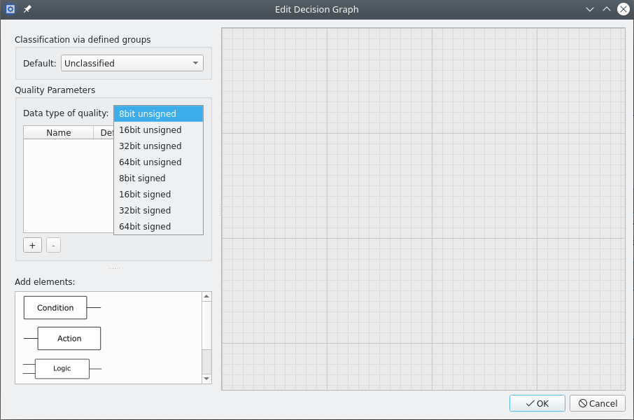
The decision graph editor of an empty decision graph will look like the following screenshot:
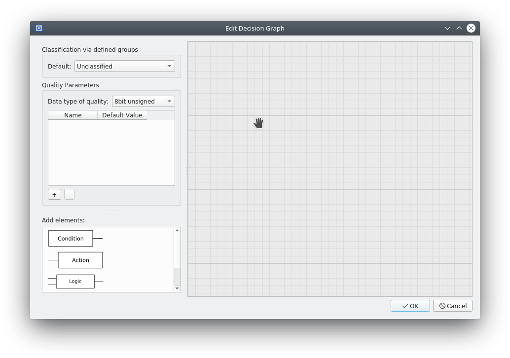
The editor is divided into four regions:
On the top left the user may specify the default group to assign to objects if no conditions apply.
At the left center the user may configure quality parameters: the integer type, how many are available, some names for these parameters that are displayed next to actions, as well as the default values for each quality parameter when no conditions apply.
On the bottom left there is a list of elements (conditions, actions, and logical operations) that may be added to the decision graph. The individual elements will be described below.
On the right side of the editor the decision graph itself is displayed. Initially this will be an empty canvas the user has to fill with the nodes required for the ruleset.
The following sub-sections describe how the decision graph editor works.
Decision Graph Nodes
A decision graph consists of nodes that form the graph. To add a node they can be dragged from the list of available nodes into the canvas:
There are three types of nodes that may be added to a decision graph:
All nodes have their inputs on the left hand side and their outputs on the right hand side. To connect two nodes drag a line from the output of one node to the input of another node.
In a decision graph all inputs of each node must be connected for the decision graph to be valid. Outputs of nodes may be left unconnected if they are not used.
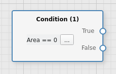
Nodes that have outputs may either be true or false. For example, a
condition node that determines if the are of an object is larger than
42 may either be true for that object (if its area is indeed larger
than 42) or false for that object (if it is not). If the node does
evaluate to true, the True output will be true and the False
output will be false. If the node evaluates to false, the True
output will be false and the False output will be true. Having each
node always have both True and False outputs avoids the need to
have a separate node for logical not operations.
Nodes may be edited by the user by using the controls shown within the
node. Condition and action nodes both have buttons with a ...
caption that allow the user to edit these in a new window. Action nodes
additionally allow the user to set the nodes priority (see below)
within the node directly. Logic nodes allow the user to swtich between
logical and and logical or via a dropdown.
The number displayed next to the node caption in parenthesis (for
example (1) or (2)) is generated automatically, has no semantic
meaning, and is present only for error reporting purposes: if there is
an error in a decision graph, the number of the node will be shown in
the error message, allowing the user to more easily track down the node
that has the specific issue. The number does not correspond to any
kind of evaluation order of the graph.
A decision graph may not have cycles: it is not allowed to connect the output of a node to one of its inputs, or to the input of another node that itself feeds the node directly or indirectly.
The various types of nodes will be described in the sections Conditions, Logical Operations, and Actions.
Defining Quality Parameters
In order to define the quality parameters one should first select the data type. Signed and unsigned integers from 8bit to 64bit are available as possible data types for the quality parameters.
All quality parameters will use the same data type.
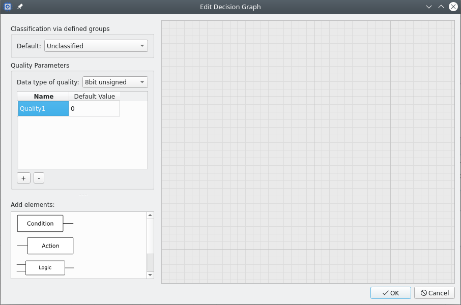
After selecting the appropriate data type, one may add a quality
parameter be clicking on the + button. After clicking on that
button a new entry will be added to the list of quality parameters. By
default a name of the form QualityX will be assigned, where X
will be replaced by a number:
It is possible to change the name of a quality parameter by starting
to type when the table cell containing the name is selected. (Pressing
F2 or double-clicking the cell will also activate the editor that
modifies the cell’s contents.)
It is important to note that the name of the quality parameter is only
present in the editor of the decision graph, so that is very easy to
see which quality value is being assigned by an action. When processing
object data the quality values will be a simple array inside the
Quality column that is added by this filter in the order seen in
the table.
In addition to the name it is also possible to set the default value of the quality parameter.
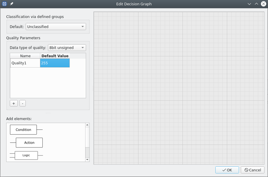
If no actions change a given quality parameter (because no conditions apply) this will be the value that is stored in the quality parameter instead. See the section Default Values and Action Priorities for further details on this.
The following screenshot shows what happens after adding a second quality parameter to the list.
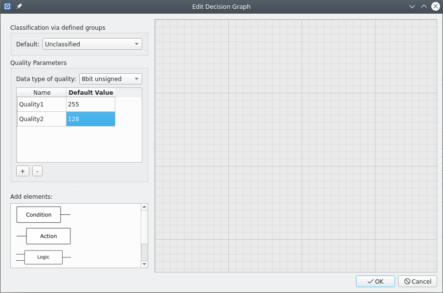
The number of quality parameters is limited by the amount of RAM available on the system.
Conditions
Condition nodes allow for matching properties of objects. After
clicking on the ... button in the condition node, a new dialog
will open that allows the user to specify the condition in detail:
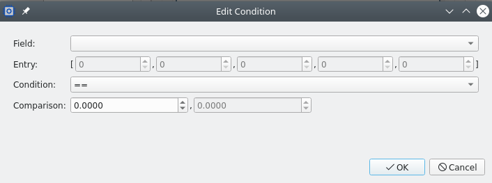
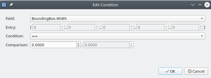
The field selector allows the user to select which column of the
input table should be matched against. For example, the following
screenshot shows how to match against the BoundingBox.Width
column:
The entry selector allows for indexing into tensor data. Most properties of an object are simply scalar numbers, but some are tensors that hold more than one numeric value. But conditions are only allowed to be attached to individual numbers. For this reason the entry selector allows the user to specify which entry of the tensor should be looked at.
The condition dropdown allows the user to select which type of comparison should be made. The following conditions are available:
==to determine if a value is exactly equal to the comparison value. Please note that for floating point numbers exact equality is often not very useful and may lead to surprising results. (For integers exact equality is very useful though.)!=is the opposite and determines if a value is distinct from the comparison value.
<to determine if a value is smaller than the comparison value,<=if it is smaller than or equal to,>if it is larger, and>=if it is larger than or equal to.The range-based options determine whether a value is within a given range or not. Instead of a single comparison value there are two comparison values and they define a range. The
inside rangevariants will be true if the value is within the specified range and theoutside rangevariants will be true if the value is outside of the specified range. Theincludedandexcludedoptions determine if the edges of the ranges are considered part of the range, or not.inside range (included)thus evaluates tovalue >= lower and value <= upper,outside range (included)evaluates tovalue < lower or value > upper,inside range (excluded)evaluates tovalue > lower and value < upper, andoutside range (excluded)evaluates tovalue <= lower or value >= upper.
Finally, the comparison value or range allows the user to specify against which the selected field the value should be compared against.
Note
It is important that the input of the Per-Object Decision Graph Filter in the model is connected. Otherwise the field selector will not be able to provide a list of available fields.
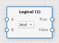
Logical Operations
A logic node is a node that performs a boolean logic operation on its
inputs. It allows for combining conditions in various manners. There
are two boolean operations available: And and Or:
For an And node to evaluate to true both of its inputs, A and
B, must be true.
For an Or node to evaluate to true one or both of its inputs, A
or B, must be true.
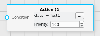
Actions
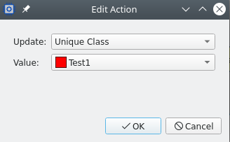
Action nodes are used to update the classification in response to a given condition. An action is only executed for a given obejct if its input evaluates to true for that object, otherwise it will be ignored.
Clicking on the ... button within the node opens a dialog that
allows the user to select what class or quality value to set. The
following screenshot shows how to set a class for the object:
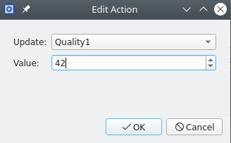
The first dropdown in the dialog allows the user to select what to update, and instead of the class the user may also select any quality value they previously defined. When selecting a quality value, instead of being offered a list of classes defined in the current model, the user is required to enter a numeric value instead:
After setting what should happen for this action, the user may also specify a priority for the action in the node. If more than one action is to be executed for a given object, the order is determined by the priority, where lower numbers are executed first. See the next section for further details on this.
Default Values and Action Priorities
When the decision graph is applied to a given object, the following steps are performed:
First the specified default values are set for the object’s class and/or the quality values. As an exception, if no action exists within the decision graph that changes an object’s class at all, the default class is not applied to the object, as it is assumed that the user only wants to use the decision graph to change quality values in that case.
After setting the default values all conditions and logical operations are evaluated in the appropriate order.
Finally all actions whose inputs have evaluated to true are applied. The order of the actions is given by the user-specified priority. Actions with lower numbers are applied first, actions with higher numbers are applied later. If two actions modify the same quality parameter (or both actions modify the class of the object), and both of their inputs evaluate to true, the action with the highest priority will be the last action to be applied, and that value will be stored.
If two actions have the same priority, the ordering between the actions is not specified, and may change whenever the decision graph is stored again. In that case the user has no control over which action will go first. If both actions modify different quality parameters this is not an issue, but if both actions modify the same quality parameter (or both modify the object’s class) either value may be used as the result of the decision graph.
Simple Example
The following simple example demonstrates how a decision graph may work:
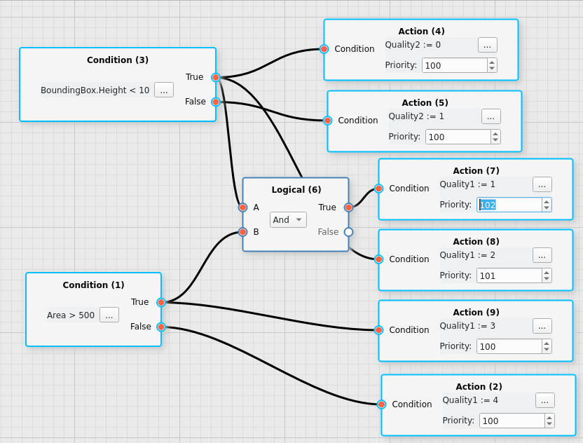
In this case the Quality2 quality parameter would depend only on
whether the obejct’s height was below 10 (pixels) or not. If
height < 10 then Quality2 would be 0, otherwise it would be
1.
The Quality1 parameter is more complicated though. Initially it
only depends on whether the object’s are is bigger than 500 (pixels).
If that is the case then Quality1 would be set to 3, otherwise
it would be set to 4. However, the first condition detecting the
object’s height also influences the quality parameter: if the object’s
height is less than 10 Quality1 will be set to 2 instead.
However, if the object’s area is also larger than 500 in addition to
its height being less than 10, Quality1 will instead be set to
1. This logic demonstrates how priority values are applied in this
case, since the priority of the actions that set Quality1 to
3 or 4 is 100, which is lower than the priority of the action
that sets it to 2 (101), which is even lower than the priority of
the action that sets it to 1 (102).
This demonstrates how a combination of boolean logic and priorities may be used to assign a specific quality value depending on a combination of various conditions.